AUTOMOBILANWENDUNGEN
Dünnschicht-Präzisionswiderstand 0,01%, TC2ppm, Drahtbondbar, Antikorrosiv, MELF. Stromsensoren, Metall,...
WeiterlesenDer MELF ist zylindrisch geformt und mit metallischen Elektroden-Leadless-Bauweise. Die Anschlussgrößen sind die gleichen wie bei SMD-Chip-Widerständen.
Es wird hergestellt, indem eine homogene Schicht aus NiCr auf einen hochwertigen Keramikkörper aufgebracht wird. Die hohe Qualität der MELF-Widerstände bietet eine ausgezeichnete elektrische und Umweltstabilität, außergewöhnliche Stabilität über die Lebensdauer hinweg, getestet unter Einfluss von Feuchtigkeit und kurzzeitiger Überlastung.
Kurze Vorlaufzeit, effektive Kostenkontrolle, Preiswettbewerbsfähigkeit

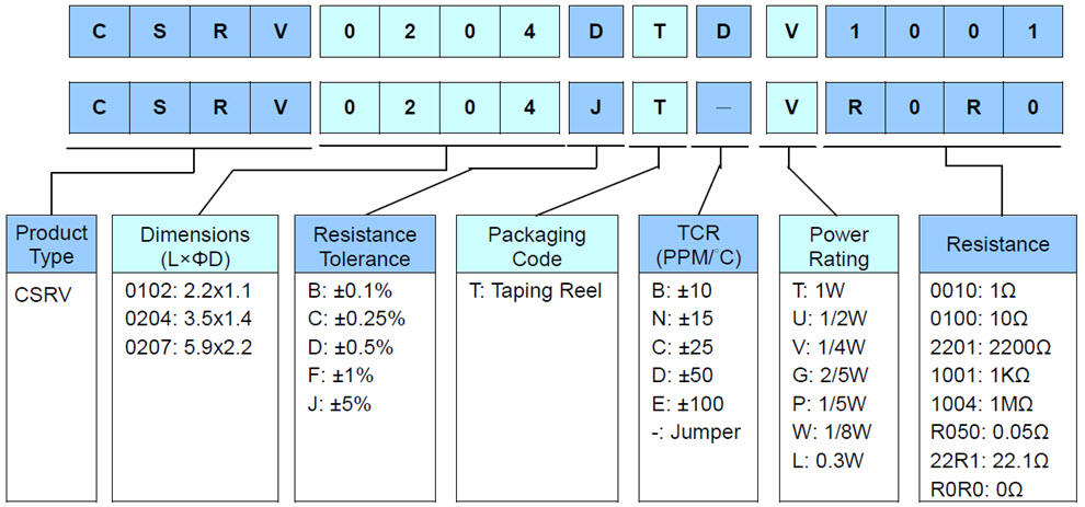
| DESCRIPTION | CSRV0102 | CSRV0204 | CSRV0207 | ||||
|---|---|---|---|---|---|---|---|
| Resistance range | 1Ω - 1MΩ; 0Ω | 0.1Ω - 3.4MΩ; 0Ω | 0.1Ω - 3.4MΩ; 0Ω | ||||
| Resistance tolerance | ± 5%;± 1%;± 0.5%;± 0.25%;± 0.1% | ||||||
| Temperature coefficient | ± 100ppm/°C; ± 50ppm/°C; ± 25ppm/°C; ± 15ppm/°C |
± 100ppm/°C; ± 50ppm/°C; ± 25ppm/°C; ± 15ppm/°C; ± 10ppm/°C |
|||||
| Operation mode | Standard | High power | Standard | High power | Standard | High power | |
| Power rating P70 | 1/8W | 1/5W | 0.3W | 1/4W | 2/5W | 1/2W | 1W |
| Operating voltage Umax. | 150V | 200V | 200V | 200V | 200V | 300V | 350V |
| Operating temperature range | -55°C ~ 155°C | ||||||
| Max. resistance change at P70 for resistance range, ΔR/R max., after 1000 h | ≦ 0.5% | ≦ 0.5% | ≦ 0.5% | ||||

| Item Type |
Power Rating at 70°C | Operating Temp. Range | Max. Operating Voltage | Max. Overload Voltage | Resistance Range | TCR (PPM/°C) | |||||||
|---|---|---|---|---|---|---|---|---|---|---|---|---|---|
| ± 0.1% (E24,E96) | ± 0.25% (E24,E96) | ± 0.5% (E24,E96) | ± 1% (E24,E96) | ± 5% (E24) | |||||||||
| 0102 | 1/8W | -55 ~ +155°C | 150V | 300V | 100Ω - 56KΩ | - | ± 15 | ||||||
| 100Ω - 82KΩ | 49.9Ω- 200KΩ | 49.9Ω - 390KΩ | - | ± 25 | |||||||||
| - | 8.2Ω - 1MΩ | ± 50 | |||||||||||
| - | 40Ω - 1MΩ | ± 100 | |||||||||||
| Jumper:2A | 0Ω (<15mΩ) | - | |||||||||||
| 0204 | 1/4W | -55 ~ +155°C | 200V | 400V | 49.9Ω - 20KΩ | ± 10 | |||||||
| 10Ω - 300KΩ | ± 15 | ||||||||||||
| 10Ω - 1MΩ | 10Ω - 3.4MΩ | 4.02Ω - 3.4MΩ | ± 25 | ||||||||||
| 10Ω - 1MΩ | 1Ω - 1MΩ | 1Ω - 3.4MΩ | 0.2Ω - 3.4MΩ | ± 50 | |||||||||
| - | 0.1Ω-1MΩ | ± 100 | |||||||||||
| Jumper:3A | 0Ω (<15mΩ) | - | |||||||||||
| 0207 | 1/2W | -55 ~ +155°C | 300V | 600V | 49.9Ω - 20KΩ | ± 10 | |||||||
| 10Ω - 300KΩ | ± 15 | ||||||||||||
| 10Ω - 1MΩ | 10Ω - 3.4MΩ | 4.02Ω - 3.4MΩ | ± 25 | ||||||||||
| 10Ω - 1MΩ | 1Ω - 1MΩ | 1Ω - 3.4MΩ | 0.2Ω - 3.4MΩ | ± 50 | |||||||||
| - | 0.1Ω - 1MΩ | ± 100 | |||||||||||
| Jumper:5A | 0Ω (<15mΩ) | - | |||||||||||
The single impulse graph is the result of the impulse of rectangular shape applied. The limit of acceptance was a shift in resistance of less than 1% from the initial value. The power applied was subject to the restrictions of the maximum permissible impulse voltage graph shown.
The continuous load graph was obtained by applying repetitive rectangular pulses where the pulse period was adjusted so that the average power dissipated in the resistor was equal to its rated power at 70℃. Again the limit of acceptance was a shift in resistance of less than 1% from the initial value.
Resistors are designed to function according to ohmic laws. This is basically true of resistors for frequencies up to 100kHz. At higher frequencies, there is an additional contribution to the impedance by an ideal resistor switched in series with a coil and both switched parallel to a capacitor. The values of the capacitance and inductance are mainly determined by the dimensions of the terminations and the conductive path length.
The environment surrounding components has a large influence on the behavior of the component on the printed-circuit board.
Resistors are tested in accordance with IEC 60115-1 using both 1.2/50us and 10/700us pulse shapes. The limit of acceptance is a shift in resistance of less than 0.5% from the initial value.

Dünnschicht-Präzisionswiderstand 0,01%, TC2ppm, Drahtbondbar, Antikorrosiv, MELF. Stromsensoren, Metall,...
Weiterlesen
Keramik-Hochfrequenz-Chip-Induktoren, kleine Größe bis 01005. Dünnschicht, Mehrschicht, Drahtgewickelt,...
Weiterlesen
Multilayer Ceramic Kondensator bietet hohe Spannung, hohe Frequenz, geringes Rauschen, hohe Güte, geringe...
Weiterlesen