
APPLICAZIONI AUTOMOTIVE
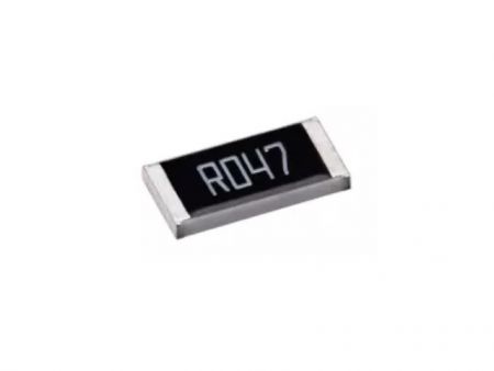
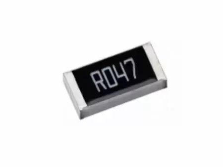
Resistore di precisione a film sottile 0.01%, TC2ppm, wirebondale, anti-corrosivo, MELF. Rilevamento...
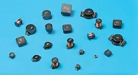
Leggi di piùCon sede a Taiwan, Viking Tech Corporation è uno dei principali produttori di Induttore a chip avvolto in filo SMD (Serie WL WL02KTH4N7) dal 1997.TS16949/ ISO9001/ ISO1400, soddisfano gli standard AEC-Q200 e i prodotti sono utilizzati per applicazioni automobilistiche e dispositivi elettronici.Viking fornisce resistori di precisione anti-zolfo, anti-sbalzo, a impulsi, ad alta tensione e ad alta potenza, inclusi resistori a film sottile/spesso, resistori automobilistici, resistori melf e resistori di rilevamento della corrente.Induttori a bassa rumorosità, bassa TC e alta potenza come induttori RF, induttori a chip, induttori di potenza, induttori variabili, induttori a chip in ferrite, induttori schermati, induttori avvolti in filo e induttori a immersione.Viking ha offerto ai clienti resistori di potenza, induttori di potenza e condensatori elettrolitici in alluminio di alta qualità con una solida reputazione.Con oltre 20 anni di esperienza, Viking è specializzata nella produzione di resistori a film sottile, resistori a chip, induttori di potenza, resistori di rilevamento corrente, resistori a film spesso, condensatori a chip e substrati ceramici.
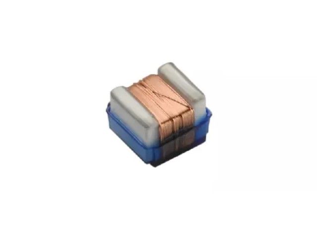
Induttore a chip ceramico avvolto in filo, induttore ad alta frequenza, induttore RF per alta SRF, eccellente Q, stabilità termica superiore. Induttanza stabile in circuiti ad alta frequenza. Design altamente stabile per esigenze critiche.
WL Series0402 ±10% 4.7nHμH 6.85 Ω 1500mA 58 83GHz
| Dimensione | Tolleranza | Induttanza | Condizione di test | DCR (Ω) max. | IDC (mA) | Q | SRF |
|---|---|---|---|---|---|---|---|
| 0402 | ±10% | 4.7nH | 250MHz | 6.85 | 1500 | 58 | 83GHz |
WL03(H) Wire Wound Chip Inductors / High Current Type
| Inductance (nH) | Tolerance | L Freq. (MHz) | Quality Factor min. | SRF (GHz) min. | DCR (Ω) max. | IDC (mA) max. |
|---|---|---|---|---|---|---|
| 1.6 | ± 5, ± 10% | 250 | 24 | 12.50 | 0.030 | 2400 |
| 3.6 | ± 5, ± 10% | 250 | 24 | 5.90 | 0.048 | 2300 |
| 3.9 | ± 5, ± 10% | 250 | 25 | 5.90 | 0.054 | 2200 |
| 6.8 | ± 5, ± 10% | 250 | 35 | 5.80 | 0.054 | 2100 |
| 7.5 | ± 5, ± 10% | 250 | 38 | 3.70 | 0.059 | 2100 |
| 8.2 | ± 5, ± 10% | 250 | 38 | 3.70 | 0.060 | 2000 |
| 10 | ± 2, ± 5, ± 10% | 250 | 38 | 3.70 | 0.071 | 2000 |
| 12 | ± 2, ± 5, ± 10% | 250 | 38 | 3.00 | 0.075 | 2000 |
| 15 | ± 2, ± 5, ± 10% | 250 | 38 | 2.80 | 0.080 | 1900 |
| 18 | ± 2, ± 5, ± 10% | 250 | 40 | 2.80 | 0.099 | 1900 |
| 22 | ± 2, ± 5, ± 10% | 250 | 42 | 2.40 | 0.099 | 1800 |
| 24 | ± 2, ± 5, ± 10% | 250 | 42 | 2.40 | 0.105 | 1800 |
WL02(H) Wire Wound Chip Inductors / High Q Type
| Inductance (nH) | Tolerance | L Freq. (MHz) | Quality Factor | SRF (GHz) min. | DCR (Ω) max. | IDC (mA) max. | |
|---|---|---|---|---|---|---|---|
| 900MHz | 1.7GHz | ||||||
| 1.0 | ± 0.2nH, ± 0.5nH, ± 5%, ± 10% | 250 | 46 | 75 | 16.0 | 0.030 | 2300 |
| 2.0 | ± 0.2nH, ± 0.5nH, ± 5%, ± 10% | 250 | 58 | 85 | 15.2 | 0.038 | 2100 |
| 2.2 | ± 0.2nH, ± 0.5nH, ± 5%, ± 10% | 250 | 60 | 86 | 15.1 | 0.038 | 2100 |
| 2.4 | ± 0.2nH, ± 0.5nH, ± 5%, ± 10% | 250 | 60 | 83 | 14.0 | 0.042 | 2000 |
| 2.7 | ± 0.2nH, ± 0.5nH, ± 5%, ± 10% | 250 | 62 | 85 | 13.0 | 0.075 | 1500 |
| 3.3 | ± 0.2nH, ± 0.5nH, ± 5%, ± 10% | 250 | 66 | 95 | 12.8 | 0.045 | 1700 |
| 3.6 | ± 0.2nH, ± 0.5nH, ± 5%, ± 10% | 250 | 65 | 94 | 11.7 | 0.045 | 1700 |
| 3.9 | ± 0.2nH, ± 0.5nH, ± 5%, ± 10% | 250 | 64 | 98 | 9.50 | 0.045 | 1700 |
| 4.3 | ± 0.5nH, ± 5%, ± 10% | 250 | 63 | 90 | 7.15 | 0.050 | 1600 |
| 4.7 | ± 0.5nH, ± 5%, ± 10% | 250 | 58 | 83 | 6.85 | 0.070 | 1500 |
| 5.1 | ± 2%, ± 5%, ± 10% | 250 | 54 | 76 | 6.80 | 0.115 | 1200 |
| 5.6 | ± 2%, ± 5%, ± 10% | 250 | 73 | 105 | 6.50 | 0.050 | 1600 |
| 6.2 | ± 2%, ± 5%, ± 10% | 250 | 73 | 100 | 5.80 | 0.055 | 1600 |
| 6.8 | ± 2%, ± 5%, ± 10% | 250 | 68 | 94 | 5.80 | 0.065 | 1500 |
| 7.5 | ± 2%, ± 5%, ± 10% | 250 | 60 | 82 | 5.40 | 0.090 | 1400 |
| 8.2 | ± 2%, ± 5%, ± 10% | 250 | 68 | 95 | 5.40 | 0.065 | 1500 |
| 8.7 | ± 2%, ± 5%, ± 10% | 250 | 68 | 95 | 5.00 | 0.065 | 1500 |
| 9.0 | ± 2%, ± 5%, ± 10% | 250 | 67 | 92 | 5.00 | 0.080 | 1400 |
| 9.5 | ± 2%, ± 5%, ± 10% | 250 | 64 | 90 | 4.70 | 0.090 | 1400 |
| 10 | ± 2%, ± 5%, ± 10% | 250 | 62 | 90 | 4.70 | 0.100 | 1300 |
| 11 | ± 2%, ± 5%, ± 10% | 250 | 68 | 98 | 4.70 | 0.065 | 1400 |
| 12 | ± 2%, ± 5%, ± 10% | 250 | 66 | 100 | 4.40 | 0.100 | 1200 |
| 13 | ± 2%, ± 5%, ± 10% | 250 | 62 | 82 | 4.20 | 0.150 | 870 |
| 15 | ± 2%, ± 5%, ± 10% | 250 | 62 | 85 | 3.90 | 0.110 | 1100 |
| 16 | ± 2%, ± 5%, ± 10% | 250 | 57 | 77 | 3.70 | 0.140 | 850 |
| 18 | ± 2%, ± 5%, ± 10% | 250 | 58 | 74 | 3.55 | 0.120 | 900 |
| 19 | ± 2%, ± 5%, ± 10% | 250 | 61 | 88 | 3.50 | 0.145 | 850 |
| 20 | ± 2%, ± 5%, ± 10% | 250 | 58 | 76 | 3.50 | 0.185 | 780 |
| 21 | ± 2%, ± 5%, ± 10% | 250 | 48 | 62 | 1.70 | 0.460 | 450 |
| 22 | ± 2%, ± 5%, ± 10% | 250 | 60 | 74 | 3.30 | 0.160 | 800 |
| 23 | ± 2%, ± 5%, ± 10% | 250 | 60 | 77 | 3.30 | 0.160 | 800 |
| 24 | ± 2%, ± 5%, ± 10% | 250 | 55 | 71 | 3.15 | 0.200 | 700 |
| 25 | ± 2%, ± 5%, ± 10% | 250 | 57 | 73 | 3.15 | 0.250 | 600 |
| 26 | ± 2%, ± 5%, ± 10% | 250 | 56 | 74 | 3.15 | 0.285 | 450 |
| 27 | ± 2%, ± 5%, ± 10% | 250 | 62 | 86 | 3.20 | 0.320 | 450 |
| 30 | ± 2%, ± 5%, ± 10% | 250 | 61 | 87 | 2.90 | 0.330 | 450 |
| 33 | ± 2%, ± 5%, ± 10% | 250 | 61 | 80 | 2.80 | 0.330 | 490 |
| 36 | ± 2%, ± 5%, ± 10% | 250 | 59 | 76 | 2.80 | 0.380 | 480 |
| 37 | ± 2%, ± 5%, ± 10% | 250 | 57 | 72 | 2.70 | 0.460 | 470 |
| 39 | ± 2%, ± 5%, ± 10% | 250 | 56 | 84 | 2.60 | 0.430 | 450 |
| 40 | ± 2%, ± 5%, ± 10% | 250 | 56 | 75 | 2.60 | 0.430 | 450 |
| 43 | ± 2%, ± 5%, ± 10% | 250 | 52 | 68 | 2.50 | 0.520 | 450 |
| 47 | ± 2%, ± 5%, ± 10% | 250 | 48 | 62 | 2.40 | 0.580 | 420 |
| 51 | ± 2%, ± 5%, ± 10% | 250 | 52 | 59 | 2.30 | 0.700 | 360 |
WL03(Q) Wire Wound Chip Inductors / High Q Type
| Inductance (nH) | Tolerance | L Freq. (MHz) | Q Typ at 250(MHz) | SRF Typ (GHz) | DCR (Ω) max. | IDC (mA) max. | 900MHz | 1.7GHz | ||
|---|---|---|---|---|---|---|---|---|---|---|
| L Typ | Q Typ | L Typ | Q Typ | |||||||
| 1.8 | ± 5, ± 10% | 250 | 23 | 16.0 | 0.033 | 2100 | 1.77 | 40 | 1.77 | 65 |
| 2.2 | ± 5, ± 10% | 250 | 13 | 15.0 | 0.180 | 900 | 2.14 | 25 | 2.12 | 35 |
| 3.0 | ± 5, ± 10% | 250 | 35 | 9.50 | 0.024 | 1000 | 2.96 | 65 | 2.97 | 85 |
| 3.3 | ± 5, ± 10% | 250 | 32 | 9.60 | 0.024 | 1900 | 3.28 | 67 | 3.32 | 104 |
| 3.6 | ± 2, ± 5, ± 10% | 250 | 40 | 9.70 | 0.031 | 1900 | 3.59 | 70 | 3.62 | 116 |
| 3.9 | ± 2, ± 5, ± 10% | 250 | 35 | 7.50 | 0.039 | 1600 | 3.88 | 68 | 3.95 | 108 |
| 4.3 | ± 2, ± 5, ± 10% | 250 | 30 | 7.50 | 0.080 | 1300 | 4.29 | 58 | 4.31 | 91 |
| 4.7 | ± 2, ± 5, ± 10% | 250 | 26 | 7.90 | 0.100 | 1100 | 4.65 | 48 | 4.71 | 75 |
| 5.1 | ± 2, ± 5, ± 10% | 250 | 40 | 8.90 | 0.036 | 1700 | 5.08 | 84 | 5.12 | 140 |
| 5.6 | ± 2, ± 5, ± 10% | 250 | 48 | 6.60 | 0.036 | 1700 | 5.6 | 87 | 5.73 | 456 |
| 6.0 | ± 2, ± 5, ± 10% | 250 | 49 | 6.00 | 0.036 | 1700 | 5.92 | 94 | 6.12 | 154 |
| 6.8 | ± 2, ± 5, ± 10% | 250 | 42 | 5.80 | 0.042 | 1400 | 6.83 | 88 | 7.05 | 143 |
| 7.2 | ± 2, ± 5, ± 10% | 250 | 48 | 5.40 | 0.052 | 1400 | 7.25 | 96 | 7.38 | 139 |
| 7.5 | ± 2, ± 5, ± 10% | 250 | 41 | 5.30 | 0.080 | 1300 | 7.55 | 81 | 7.85 | 12 |
| 8.2 | ± 2, ± 5, ± 10% | 250 | 46 | 5.90 | 0.054 | 1400 | 8.21 | 96 | 8.39 | 148 |
| 8.7 | ± 2, ± 5, ± 10% | 250 | 46 | 5.50 | 0.054 | 1400 | 8.73 | 97 | 9.00 | 149 |
| 9.1 | ± 2, ± 5, ± 10% | 250 | 40 | 5.10 | 0.037 | 1400 | 9.18 | 76 | 9.64 | 109 |
| 9.5 | ± 2, ± 5, ± 10% | 250 | 49 | 4.90 | 0.053 | 1400 | 9.56 | 98 | 9.99 | 149 |
| 10 | ± 2, ± 5, ± 10% | 250 | 49 | 4.30 | 0.048 | 1400 | 10.16 | 90 | 10.64 | 142 |
| 11 | ± 2, ± 5, ± 10% | 250 | 41 | 4.10 | 0.058 | 1400 | 11.06 | 78 | 11.82 | 108 |
| 12 | ± 2, ± 5, ± 10% | 250 | 37 | 4.10 | 0.088 | 1100 | 12.26 | 69 | 13.2 | 91 |
| 15 | ± 2, ± 5, ± 10% | 250 | 48 | 3.60 | 0.078 | 1200 | 15.41 | 83 | 17.2 | 124 |
| 16 | ± 2, ± 5, ± 10% | 250 | 45 | 3.50 | 0.085 | 1100 | 16.37 | 77 | 18.7 | 116 |
| 18 | ± 2, ± 5, ± 10% | 250 | 41 | 3.30 | 0.066 | 1200 | 18.56 | 76 | 20.9 | 100 |
| 22 | ± 2, ± 5, ± 10% | 250 | 44 | 3.15 | 0.140 | 850 | 22.7 | 77 | 25.9 | 88 |
| 23 | ± 2, ± 5, ± 10% | 250 | 40 | 3.00 | 0.183 | 850 | 24 | 69 | 29.53 | 80 |
| 24 | ± 2, ± 5, ± 10% | 250 | 42 | 2.95 | 0.074 | 1100 | 24.9 | 77 | 28.9 | 91 |
| 27 | ± 2, ± 5, ± 10% | 250 | 44 | 2.80 | 0.150 | 780 | 28.4 | 74 | 34.0 | 84 |
| 30 | ± 2, ± 5, ± 10% | 250 | 49 | 2.80 | 0.130 | 920 | 31.5 | 82 | 37.9 | 82 |
| 33 | ± 2, ± 5, ± 10% | 250 | 45 | 2.70 | 0.170 | 680 | 34.9 | 76 | 42.9 | 80 |
| 36 | ± 2, ± 5, ± 10% | 250 | 44 | 2.50 | 0.225 | 720 | 38.5 | 69 | 50.0 | 64 |
| 39 | ± 2, ± 5, ± 10% | 250 | 48 | 2.45 | 0.19 | 680 | 41.5 | 78 | 51.9 | 74 |
| 43 | ± 2, ± 5, ± 10% | 250 | 45 | 2.45 | 0.17 | 810 | 45.7 | 83 | 58.1 | 76 |
| 47 | ± 2, ± 5, ± 10% | 200 | 47 | 2.30 | 0.24 | 680 | 50.6 | 77 | 66.9 | 72 |
| 51 | ± 2, ± 5, ± 10% | 200 | 49 | 2.30 | 0.28 | 660 | 54.6 | 73 | 71.3 | 62 |
| 56 | ± 2, ± 5, ± 10% | 200 | 50 | 2.20 | 0.30 | 610 | 60.3 | 74 | 79.9 | 56 |
| 68 | ± 2, ± 5, ± 10% | 200 | 46 | 2.00 | 0.33 | 600 | 75.5 | 73 | 113.3 | 49 |
| 72 | ± 2, ± 5, ± 10% | 150 | 46 | 1.90 | 0.42 | 550 | 80.8 | 69 | - | - |
| 75 | ± 2, ± 5, ± 10% | 150 | 46 | 1.90 | 0.52 | 500 | 84.6 | 71 | - | - |
| 82 | ± 2, ± 5, ± 10% | 150 | 45 | 1.80 | 0.46 | 510 | 94 | 62 | - | - |
| 91 | ± 2, ± 5, ± 10% | 150 | 45 | 1.65 | 0.58 | 440 | 103 | 64 | - | - |
| 100 | ± 2, ± 5, ± 10% | 150 | 49 | 1.70 | 0.54 | 470 | 114 | 69 | - | - |
| 110 | ± 2, ± 5, ± 10% | 150 | 47 | 1.60 | 0.58 | 440 | 126.2 | 63 | - | - |
| 120 | ± 2, ± 5, ± 10% | 150 | 47 | 1.55 | 0.72 | 420 | 142.4 | 61 | - | - |
| 150 | ± 2, ± 5, ± 10% | 150 | 47 | 1.35 | 0.82 | 390 | 188.8 | 57 | - | - |
| 180 | ± 2, ± 5, ± 10% | 100 | 48 | 1.30 | 1.50 | 310 | 232.2 | 50 | - | - |
| 200 | ± 2, ± 5, ± 10% | 100 | 47 | 1.25 | 2.00 | 280 | 265 | 47 | - | - |
| 210 | ± 2, ± 5, ± 10% | 100 | 48 | 1.20 | 2.00 | 280 | 288 | 45 | - | - |
| 220 | ± 2, ± 5, ± 10% | 100 | 47 | 1.10 | 2.00 | 280 | 315 | 41 | - | - |
| 250 | ± 2, ± 5, ± 10% | 100 | 45 | 1.05 | 3.00 | 240 | - | - | - | - |
| 270 | ± 2, ± 5, ± 10% | 100 | 46 | 1.05 | 2.25 | 260 | - | - | - | - |
| 300 | ± 2, ± 5, ± 10% | 100 | 47 | 0.99 | 2.80 | 220 | - | - | - | - |
| 330 | ± 2, ± 5, ± 10% | 100 | 46 | 0.93 | 3.60 | 180 | - | - | - | - |
| 360 | ± 2, ± 5, ± 10% | 100 | 47 | 0.93 | 4.00 | 170 | - | - | - | - |
| 390 | ± 2, ± 5, ± 10% | 100 | 47 | 0.88 | 4.00 | 170 | - | - | - | - |
WL05(H) Wire Wound Chip Inductors / High Q Type
| Inductance (nH) | Tolerance | L Freq. (MHz) | Quality Factor min. | SRF (GHz) min. | DCR (Ω) max. | IDC (mA) max. |
|---|---|---|---|---|---|---|
| 2.5 | ± 5, ± 10% | 250 | 80 @ 1500MHz | 6.00 | 0.020 | 1600 |
| 5.6 | ± 5, ± 10% | 250 | 98 @ 1500MHz | 6.00 | 0.035 | 1600 |
| 6.2 | ± 5, ± 10% | 250 | 88 @ 1000MHz | 4.75 | 0.035 | 1600 |
| 6.8 | ± 5, ± 10% | 250 | 80 @ 1000MHz | 4.40 | 0.035 | 1600 |
| 8.2 | ± 5, ± 10% | 250 | 75 @ 1000MHz | 3.00 | 0.075 | 1000 |
| 10 | ± 5, ± 10% | 250 | 80 @ 1000MHz | 3.00 | 0.060 | 1600 |
| 12 | ± 5, ± 10% | 250 | 80 @ 1000MHz | 3.00 | 0.045 | 1600 |
| 15 | ± 2, ± 5, ± 10% | 250 | 80 @ 1000MHz | 2.80 | 0.100 | 1200 |
| 16 | ± 2, ± 5, ± 10% | 250 | 72 @ 500MHz | 2.95 | 0.060 | 1500 |
| 18 | ± 2, ± 5, ± 10% | 250 | 75 @ 500MHz | 2.55 | 0.060 | 1400 |
| 20 | ± 2, ± 5, ± 10% | 250 | 70 @ 500MHz | 2.05 | 0.055 | 1400 |
| 22 | ± 2, ± 5, ± 10% | 250 | 80 @ 500MHz | 2.00 | 0.100 | 1200 |
| 27 | ± 2, ± 5, ± 10% | 250 | 75 @ 500MHz | 2.00 | 0.070 | 1300 |
| 30 | ± 2, ± 5, ± 10% | 250 | 65 @ 500MHz | 1.95 | 0.095 | 1200 |
| 39 | ± 2, ± 5, ± 10% | 250 | 65 @ 500MHz | 1.60 | 0.110 | 1100 |
| 48 | ± 2, ± 5, ± 10% | 200 | 65 @ 500MHz | 1.40 | 0.095 | 1200 |
| 51 | ± 2, ± 5, ± 10% | 200 | 65 @ 500MHz | 1.40 | 0.120 | 1000 |
WL08(H) Wire Wound Chip Inductors / High Q Type
| Inductance (nH) | Tolerance | L Freq. (MHz) | Quality Factor min. | SRF (GHz) min. | DCR (Ω) max. | IDC (mA) max. |
|---|---|---|---|---|---|---|
| 3.0 | ± 5, ± 10% | 50 | 70 @ 1500MHz | 6.00 | 0.04 | 1600 |
| 3.9 | ± 5, ± 10% | 50 | 75 @ 1500MHz | 6.00 | 0.05 | 1600 |
| 4.1 | ± 5, ± 10% | 50 | 75 @ 1500MHz | 6.00 | 0.05 | 1600 |
| 7.8 | ± 5, ± 10% | 50 | 75 @ 500MHz | 3.80 | 0.05 | 1600 |
| 10 | ± 2, ± 5, ± 10% | 50 | 60 @ 500MHz | 3.60 | 0.06 | 1600 |
| 12 | ± 2, ± 5, ± 10% | 50 | 70 @ 500MHz | 2.80 | 0.06 | 1500 |
| 18 | ± 2, ± 5, ± 10% | 50 | 62 @ 350MHz | 2.70 | 0.07 | 1400 |
| 22 | ± 2, ± 5, ± 10% | 50 | 62 @ 350MHz | 2.05 | 0.07 | 1400 |
| 33 | ± 2, ± 5, ± 10% | 50 | 75 @ 350MHz | 1.70 | 0.09 | 1300 |
| 39 | ± 2, ± 5, ± 10% | 50 | 75 @ 350MHz | 1.30 | 0.09 | 1300 |
| 47 | ± 2, ± 5, ± 10% | 50 | 75 @ 350MHz | 1.45 | 0.12 | 1200 |
| 56 | ± 2, ± 5, ± 10% | 50 | 75 @ 350MHz | 1.23 | 0.12 | 1200 |
| 68 | ± 2, ± 5, ± 10% | 50 | 80 @ 350MHz | 1.15 | 0.13 | 1100 |
| 82 | ± 2, ± 5, ± 10% | 50 | 80 @ 350MHz | 1.06 | 0.16 | 1100 |
| 100 | ± 2, ± 5, ± 10% | 50 | 50 @ 350MHz | 0.82 | 0.16 | 1000 |
| 120 | ± 2, ± 5, ± 10% | 100 | 50 @ 100MHz | 0.82 | 0.16 | 1000 |
☑ Parts (3.0nH, 7.8nH) are wound on a low profile bobbin. (Max 2.41 x 2.01 x 1.09)
Electrical Performance Test
| Item | Requirement | Test Method |
|---|---|---|
| Inductance | Refer to standard electrical characteristic spec. | HP4286/E4982A |
| Q | HP4286/E4982A | |
| SRF | HP4287/E4982A | |
| DC Resistance RDC | Micro-Ohm meter (Gom-801G)/E4982A | |
| Rated Current IDC | Applied the current to coils, the temperature of coil increases ΔT15°C (Ta = 25°C). | |
| Over Load | Inductors shall have no evidence of electrical and mechanical damage | Applied 2 times of rated allowed DC current to inductor for a period of 5 minutes |
| Withstanding Voltage | Inductors shall be no evidence of electrical and mechanical damage. | AC voltage of 500 VAC applied between inductors terminal and case for 1 min. |
| Insulation Resistance | 1000M ohm min. | 100 VDC applied between inductor terminal and case |
Mechanical Performance Test
| Item | Requirement | Test Method |
|---|---|---|
| Vibration | Appearance: No damage L change: within ± 5% Q change: within ± 10% | Test device shall be soldered on the substrate Oscillation Frequency: 10 to 55 to 10Hz for 1 min. Amplitude: 1.5 mm Time: 2 hrs for each axis (X, Y & Z), total 6 hrs |
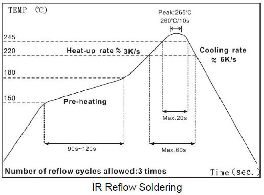
| Resistance to Soldering Heat | Solder Temperature: 260± 5°C Immersion Time: 10± 2 seconds | |
| Component Adhesion (Push Test) | 1 lbs. For 0402 2 lbs. For 0603 3 lbs. For the rest | The device should be soldered (260± 5°C for 10 seconds) to a tinned copper subs rate. A dynamiter force gauge should be applied to the side of the component. The device must with stand a minimum force of 2 or 4 pounds without a failure of adhesion on termination |
| Drop | No damage | Dropping chip by each side and each corner. Drop 10 times in total Drop height: 100 cm Drop weight: 125 g |
| Solderability | 90% covered with solder | Inductor shall be dipped in a melted solder bath at 245± 5°C for 3 seconds |
| Resistance to Solvent | No damage on appearance and marking | MIL-STD-202, Method 215 |
Climatic Test
| Item | Requirement | Item | ||||||||||||||
|---|---|---|---|---|---|---|---|---|---|---|---|---|---|---|---|---|
| Temperature Characteristic | Appearance: No damage L change: within ± 10% Q change: within ± 20% | -40°C ~ +125°C | ||||||||||||||
| Humidity | Temperature: 40± 2°C Relative Humidity: 90 ~ 95% Time: 96± 2 hrs Measured after exposure in the room condition for 2 hrs | |||||||||||||||
| Low Temperature Storage | Temperature: -40± 2°C Time: 96± 2 hrs Inductors are tested after 1 hour at room temperature | |||||||||||||||
| Thermal Shock | One cycle:
Total: 5 cycles | |||||||||||||||
| High Temperature Storage | Temperature: 125± 2°C Time: 96± 2 hrs Measured after exposure in the room condition for 1hour | |||||||||||||||
| High Temperature Load Life | There should be no evidence of short of open circuit. | Temperature: 85± 2°C Time: 1000± 12 hrs Load: Allowed DC current | ||||||||||||||
| Damp Heat with Load | Temperature: 40± 2°C Relative Humidity: 90 ~ 95% Time: 1000± 12 hrs Load: Allowed DC current |
☑ Storage Temperature: 15 ~ 28°C; Humidity < 80%RH
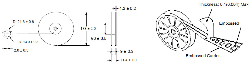
Reel Dimensions & Packaging Quantity (Unit : mm)
Paper Tape specification and Packaging Quantity (Unit : mm)
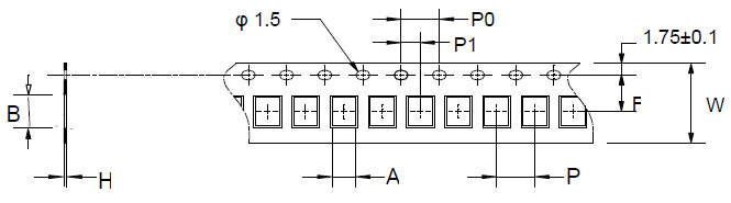
| Type | A | B | H | F | P | P0 | P1 | W | Reel (EA) |
|---|---|---|---|---|---|---|---|---|---|
| WL02 | 0.81 | 1.23 | 0.73 | 3.50 | 2.00 | 4.00 | 2.00 | 8.00 | 4,000 |
| WL03 | 1.35 | 1.95 | 0.95 | 3.50 | 4.00 | 4.00 | 2.00 | 8.00 | 4,000 |
Embossed Plastic Tape specification and Packaging Quantity (Unit : mm)
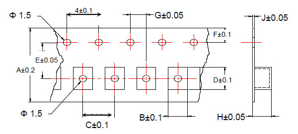
| Type | A | B | C | D | E | F | G | H | J | Reel (EA) |
|---|---|---|---|---|---|---|---|---|---|---|
| WL05 | 8 | 1.85 | 4 | 2.30 | 3.5 | 1.75 | 2 | 1.45 | 0.23 | 2,000 |
| WL05 (H) | 8 | 1.85 | 4 | 2.30 | 3.5 | 1.75 | 2 | 1.45 | 0.23 | 2,000 |
| WL08 | 8 | 2.70 | 4 | 2.80 | 3.5 | 1.75 | 2 | 2.00 | 0.23 | 2,000 |
| WL08 (H) | 8 | 2.70 | 4 | 2.80 | 3.5 | 1.75 | 2 | 2.00 | 0.23 | 2,000 |

Resistore di precisione a film sottile 0.01%, TC2ppm, wirebondale, anti-corrosivo, MELF. Rilevamento...
Leggi di più
Induttori a chip ceramici ad alta frequenza, dimensioni ridotte fino a 01005. Induttore a film sottile,...
Leggi di più
Il condensatore ceramico multistrato offre alta tensione, alta frequenza, basso rumore, alta Q, basso...
Leggi di più