

APLICACIONES AUTOMOTRICES
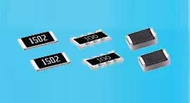
Resistor de precisión de película delgada 0.01%, TC2ppm, con cable de unión, anticorrosivo, MELF. Detección...
Lee masCon sede en Taiwán, Viking Tech Corporation es uno de los principales fabricantes de Inductor de potencia tipo bobina desde 1997.Cumple con las normas TS16949/ ISO9001/ ISO1400, cumple con los estándares AEC-Q200 y los productos se utilizan en aplicaciones automotrices y de dispositivos electrónicos.Viking ofrece resistencias de precisión anti-sulfuro, anti-sobretensión, de pulso, de alto voltaje y alta potencia, incluyendo resistencias de película delgada/ gruesa, resistencias automotrices, resistencias MELF y resistencias de detección de corriente.Inductores de bajo ruido, bajo coeficiente de temperatura (TC), alta potencia, como inductores de RF, inductores de chip, inductores de potencia, inductores variables, inductores de chip de ferrita, inductores blindados, inductores de hilo enrollado e inductores de inmersión.Viking ha estado ofreciendo a los clientes resistencias de potencia, inductores de potencia y condensadores electrolíticos de aluminio de alta calidad con una sólida reputación.Con más de 20 años de experiencia, Viking se especializa en la fabricación de Resistores de Película Delgada, Resistores de Chip, Inductores de Potencia, Resistores de Sensado de Corriente, Resistores de Película Gruesa, Capacitores de Chip y Substratos Cerámicos.
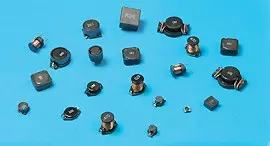
Inductor de chip de ferrita bobinada, alta potencia, tamaños pequeños, circuito magnético cerrado evita la diafonía, adecuado para instalación de alta densidad y soldadura de reflujo. Utilizado en todo tipo de dispositivos electrónicos, computadoras, convertidores.
MLP Series1004 ±20% 0.68μH 0.044 Ω 3.87A 3.06A
| Tamaño | Tolerancia | Inductancia | Condición de prueba | DCR (Ω) máx. | I sat (A) máx. | I rms (A) máx. |
|---|---|---|---|---|---|---|
| 1004 | ±20% | 0.68 | 1MHz, 1mA | 0.044 | 3.87 | 3.06 |
MLPH06 (0806) Wire Wound Type Power Inductor
| Codes | Inductance (uH) | Tolerance | Test Condition | DCR (mΩ) max. | Isat (A) max. | Irms (A) max. |
|---|---|---|---|---|---|---|
| R47 | 0.47 | ± 20% | 1MHz, 1V | 30 | 5.30 | 4.05 |
| 1R0 | 1.0 | ± 20% | 1MHz, 1V | 60 | 3.30 | 3.00 |
| 1R5 | 1.5 | ± 20% | 1MHz, 1V | 99 | 3.10 | 2.20 |
| 2R2 | 2.2 | ± 20% | 1MHz, 1V | 140 | 2.45 | 2.00 |
MLPH04 (1004) Wire Wound Type Power Inductor
| R47 | 0.47 | ± 20% | 1MHz, 1V | 29 | 6.00 | 4.40 |
| 1R0 | 1.0 | ± 20% | 1MHz, 1V | 52 | 4.00 | 3.10 |
| 2R2 | 2.2 | ± 20% | 1MHz, 1V | 110 | 3.00 | 2.10 |
MLPH08 (1008) Wire Wound Type Power Inductor
| Codes | Inductance (uH) | Tolerance | Test Condition | DCR (mΩ) max. | Isat (A) max. | Irms (A) max. |
|---|---|---|---|---|---|---|
| R47 | 0.47 | ± 20% | 1MHz, 1V | 22 | 6.20 | 4.90 |
| 1R0 | 1.0 | ± 20% | 1MHz, 1V | 44 | 4.30 | 3.30 |
| 2R2 | 2.2 | ± 20% | 1MHz, 1V | 89 | 3.20 | 2.20 |
Operating Temperature range: -40°C to +125°C
Electrical Performance Test
| Item | Requirement | Test Method |
|---|---|---|
| Inductance | Refer to standard electrical characteristic spec. | HP4285A |
| DC Resistance RDC | micro-ohm meter. | |
| Isat | DC current will cause a 30% inductance reduction form initial value. | |
| Irms | DC current will cause coil temp. rising to 40℃ whichever is smaller. |
Mechanical Performance Test
| Item | Requirement | Test Method |
|---|---|---|
| Resistance to Soldering Heat | Appearance: No damage More than 95% of the terminal. Electrode should be covered with solder. Inductance: within ± 20% of initial value | Flux: Rosin Solder Temperature: 260 ± 5°C Immersion Time: 10 ± 1 sec. |
| Adhesive Test | No mechanical damage Soldering the products on PCB after the pulling test force>5N | Reflow temperature: 245°C it shall be soldered on the substrate applying direction parallel to the substrate Apply force(F): 5 N Test time: 10 sec |
| Temperature Cycle | No mechanical damage Inductance: within ± 20% of initial value | Temperature: -50 ~ 125°C for 30 minutes each Cycle: 500cycles Measurement: at ambient temperature 24 hours after test completion |
| Dry Heat Test | Temperature: 85 ± 2°C Testing time: 500 hrs Applied current: full rated current Measurement: at ambient temperature 24 hours after test completion | |
| Humidity Test | Temperature: 60 ± 2°C, Humidity: 90 ~ 95% RH Testing time: 500 hrs Applied current: full rated current Measurement: at ambient temperature 24 hours after test completion |
☑Storage Temperature: 5~40°C ; Humidity:<65%RH
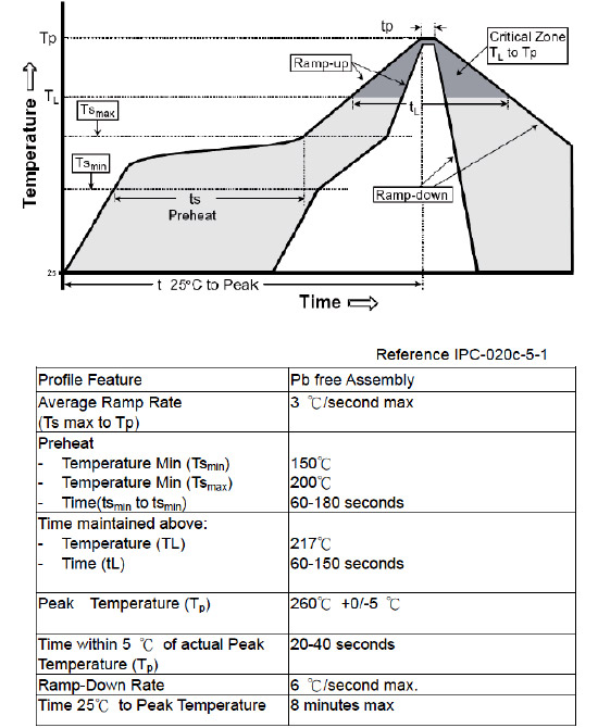
Recommendable Reflow Soldering
Reel Specifications (Unit: mm)
| Type | A | B | C | W | T | Quantity (EA) | 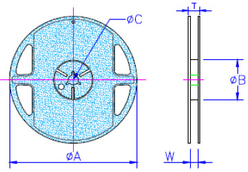 |
|---|---|---|---|---|---|---|---|
| MLP03 | 178 ± 1 | 60.0 + 0.5 | 13.0 ± 0.2 | 9.00 ± 0.5 | 12.0 ± 0.15 | 3,000 | |
| MLP05 | 178 ± 1 | 60.0 + 0.5 | 13.0 ± 0.2 | 9.00 ± 0.5 | 12.0 ± 0.15 | 3,000 | |
| MLP(H)06 | 178 ± 1 | 60.0 + 0.5 | 13.0 ± 0.2 | 9.00 ± 0.5 | 12.0 ± 0.15 | 3,000 | |
| MLP(H)04 | 178 ± 1 | 60.0 + 0.5 | 13.0 ± 0.2 | 9.00 ± 0.5 | 12.0 ± 0.15 | 3,000 | |
| MLP(H)08 | 178 ± 1 | 60.0 + 0.5 | 13.0 ± 0.2 | 9.00 ± 0.5 | 12.0 ± 0.15 | 3,000 | |
| MLP10 | 178 ± 1 | 60.0 + 0.5 | 13.0 ± 0.2 | 9.00 ± 0.5 | 12.0 ± 0.15 | 3,000 |
Tape Specifications (Unit: mm)
| Type | A0 | B0 | K0 | t | 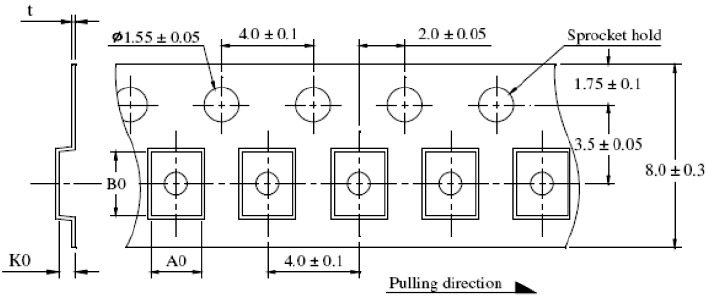 |
|---|---|---|---|---|---|
| MLP03 | 1.45 ± 0.10 | 2.20 ± 0.10 | 1.12 ± 0.10 | 0.22 ± 0.05 | |
| MLP05 | 1.45 ± 0.10 | 2.20 ± 0.10 | 1.12 ± 0.10 | 0.22 ± 0.05 | |
| MLP06 | 1.80 ± 0.10 | 2.20 ± 0.10 | 1.15 ± 0.10 | 0.22 ± 0.05 | |
| MLPH06 | 1.82 ± 0.05 | 2.23 ± 0.05 | 1.15 ± 0.05 | 0.22 ± 0.05 | |
| MLP04 | 2.50 ± 0.10 | 3.00 ± 0.10 | 1.60 ± 0.10 | 0.25 ± 0.05 | |
| MLPH04 | 2.25 ± 0.05 | 2.80 ± 0.10 | 1.35 ± 0.10 | 0.22 ± 0.05 | |
| MLP08 | 2.50 ± 0.10 | 3.00 ± 0.10 | 1.60 ± 0.10 | 0.25 ± 0.05 | |
| MLPH08 | 2.25 ± 0.05 | 2.80 ± 0.10 | 1.35 ± 0.10 | 0.22 ± 0.05 | |
| MLP10 | 2.80 ± 0.10 | 3.45 ± 0.10 | 1.34 ± 0.10 | 0.23 ± 0.05 |

Resistor de precisión de película delgada 0.01%, TC2ppm, con cable de unión, anticorrosivo, MELF. Detección...
Lee mas
Inductores de chip de alta frecuencia cerámicos, tamaño pequeño hasta 01005. Película delgada, multicapa,...
Lee mas
El capacitor cerámico multicapa ofrece alta tensión, alta frecuencia, bajo ruido, alto Q, baja TCR....
Lee mas