

APLICAÇÕES AUTOMOTIVAS
Resistor de precisão de filme fino 0,01%, TC2ppm, wirebondale, Anti-Corrosivo, MELF. Detecção de corrente,...
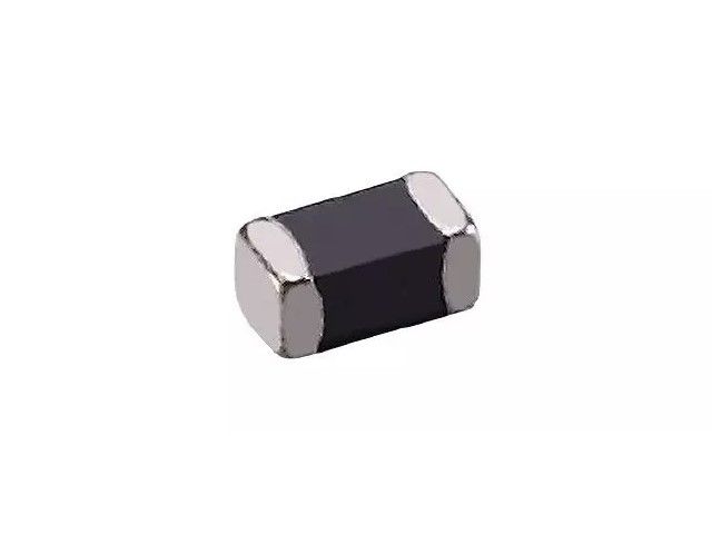
consulte Mais informaçãoCom sede em Taiwan, Viking Tech Corporation é um dos principais fabricantes de Indutor de Chip de Ferrite Multicamada (Série ML ML03MT56N) desde 1997.TS16949/ ISO9001/ ISO1400, atendem aos padrões AEC-Q200 e os produtos são utilizados em aplicações automotivas e de dispositivos eletrônicos.A Viking oferece resistores de precisão anti-sulfur, anti-surge, pulse, alta tensão e alta potência, incluindo resistores de filme fino/espesso, resistores automotivos, resistores melf e resistores de detecção de corrente.Indutores de baixo ruído, baixo TC, alta potência, como indutores de RF, indutores de chip, indutores de potência, indutores variáveis, indutores de chip de ferrite, indutores blindados, indutores de enrolamento de fio e indutores de mergulho.A Viking tem oferecido aos clientes resistores de potência, indutores de potência e capacitores eletrolíticos de alumínio de alta qualidade, com uma sólida reputação.Com mais de 20 anos de experiência, Viking é especializada na fabricação de Resistor de Chip de Filme Fino, Resistor de Chip, Indutor de Potência, Resistor de Sensor de Corrente, Resistor de Filme Grosso, Capacitor de Chip e Substrato Cerâmico.
Indutor de chip de ferrite multicamada, tamanhos pequenos, circuito magnético fechado evita interferência cruzada, adequado para instalação de alta densidade e soldagem por refluxo. Usado em todos os tipos de dispositivos eletrônicos, computação, conversores.
ML Series0603 ±20%nH 56μH 0.3 Ω 50mA 10 255MHz 50MHz, 200mV MHz
| Tamanho | Tolerância | Indutância | DCR (Ω) máx. | IDC (mA) | Q | SRF | Frequência L/Q (MHz) |
|---|---|---|---|---|---|---|---|
| 0603 | ±20% | 56 | 0.3 | 50 | 10 | 255MHz | 50MHz, 200mV |
MLH05 Multilayer Ferrite Chip Inductors Type(□:Tolerance):
| Part No. | Inductance (uH) | Tolerance | Test Freq. | SRF (MHz) min. | DCR (Ω) max. | IDC (mA) max. |
|---|---|---|---|---|---|---|
| MLH05□TR47 | 0.47 | ± 20% | 1MHz, 250mV | 100 | 0.125 | 1100 |
| MLH05□TR68 | 0.68 | ± 20% | 1MHz, 250mV | 100 | 0.150 | 1000 |
| MLH05□TR82 | 0.82 | ± 20% | 1MHz, 250mV | 90 | 0.175 | 900 |
| MLH05□T1R0 | 1.0 | ± 20% | 1MHz, 250mV | 90 | 0.200 | 800 |
| MLH05□T1R2 | 1.2 | ± 20% | 1MHz, 250mV | 80 | 0.200 | 800 |
| MLH05□T1R5 | 1.5 | ± 20% | 1MHz, 250mV | 70 | 0.275 | 700 |
| MLH05□T1R8 | 1.8 | ± 20% | 1MHz, 250mV | 60 | 0.275 | 700 |
| MLH05□T2R2 | 2.2 | ± 20% | 1MHz, 250mV | 50 | 0.313 | 600 |
| MLH05□T3R3 | 3.3 | ± 20% | 1MHz, 250mV | 40 | 0.275 | 500 |
| MLH05□T4R7 | 4.7 | ± 20% | 1MHz, 250mV | 30 | 0.375 | 500 |
☑ Operating temperature range: -40 ~ +125°C
MLH06 Multilayer Ferrite Chip Inductors Type(□:Tolerance):
| Part No. | Inductance (uH) | Tolerance | Test Freq. | SRF (MHz) min. | DCR (Ω) max. | IDC (mA) max. |
|---|---|---|---|---|---|---|
| MLH06□TR47 | 0.47 | ± 20% | 1MHz, 250mV | 100 | 0.182 | 1500 |
| MLH06□TR68 | 0.68 | ± 20% | 1MHz, 250mV | 90 | 0.195 | 1500 |
| MLH06□TR82 | 0.82 | ± 20% | 1MHz, 250mV | 80 | 0.208 | 1500 |
| MLH06□T1R0 | 1.0 | ± 20% | 1MHz, 250mV | 60 | 0.208 | 1400 |
| MLH06□T1R2 | 1.2 | ± 20% | 1MHz, 250mV | 60 | 0.208 | 1400 |
| MLH06□T1R5 | 1.5 | ± 20% | 1MHz, 250mV | 50 | 0.260 | 1200 |
| MLH06□T1R8 | 1.8 | ± 20% | 1MHz, 250mV | 50 | 0.260% | 1200 |
| MLH06□T2R2 | 2.2 | ± 20% | 1MHz, 250mV | 40 | 0.286 | 1200 |
| MLH06□T3R3 | 3.3 | ± 20% | 1MHz, 250mV | 30 | 0.312 | 1100 |
| MLH06□T4R7 | 4.7 | ± 20% | 1MHz, 250mV | 20 | 0.390 | 1100 |
☑ Operating temperature range: -40 ~ +125°C
MLH08 Multilayer Ferrite Chip Inductors Type(□:Tolerance):
| Part No. | Inductance (uH) | Tolerance | Test Freq. | SRF (MHz) min. | DCR (Ω) max. | IDC (mA) max. |
|---|---|---|---|---|---|---|
| MLH08□TR47 | 0.47 | ± 20% | 1MHz, 250mV | 100 | 0.088 | 1800 |
| MLH08□TR68 | 0.68 | ± 20% | 1MHz, 250mV | 90 | 0.113 | 1700 |
| MLH08□TR82 | 0.82 | ± 20% | 1MHz, 250mV | 80 | 0.125 | 1700 |
| MLH08□T1R0 | 1.0 | ± 20% | 1MHz, 250mV | 60 | 0.138 | 1600 |
| MLH08□T1R2 | 1.2 | ± 20% | 1MHz, 250mV | 60 | 0.138 | 1600 |
| MLH08□T1R5 | 1.5 | ± 20% | 1MHz, 250mV | 50 | 0.163 | 1500 |
| MLH08□T1R8 | 1.8 | ± 20% | 1MHz, 250mV | 50 | 0.163 | 1500 |
| MLH08□T2R2 | 2.2 | ± 20% | 1MHz, 250mV | 40 | 0.213 | 1300 |
| MLH08□T3R3 | 3.3 | ± 20% | 1MHz, 250mV | 30 | 0.200 | 1200 |
| MLH08□T4R7 | 4.7 | ± 20% | 1MHz, 250mV | 25 | 0.250 | 1100 |
☑ Operating temperature range: -40 ~ +125°C
Electrical Performance Test
| Item | Requirement | Test Method |
|---|---|---|
| Inductance | Refer to standard electrical characteristic spec. | HP4291B |
| Q | HP4291B | |
| SRF | HP4291B | |
| DC Resistance RDC | Agilent 34401A |
Mechanical Performance Test
| Item | Requirement | Test Method |
|---|---|---|
| Resistance to Soldering Heat | Appearance: No damage More than 75% of the terminal. Electrode should be covered with solder. | Pre-heating: 150°C, 1min. Solder Composition: Sn/Ag3.0/Cu0.5 (Pb-Free) Solder Temperature: 260± 5°C (Pb-Free) Immersion Time: 10± 1 sec. |
| Solderability | The electrodes shall be at least 90% covered with new solder coating | Pre-heating: 150°C, 1min. Solder Composition: Sn/Ag3.0/Cu0.5 (Pb-Free) Solder Temperature: 245± 5°C (Pb-Free) Immersion Time: 4± 1 sec. |
| Flexure Strength | The forces applied on the right conditions must not damage the terminal electrode and the ferrite. | 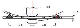 Test device shall be soldered on the substrate |
| Vibration | Test device shall be soldered on the substrate Oscillation Frequency: 10 to 55 to 10Hz for 1 min. Amplitude: 1.5 mm Time: 2 hrs for each axis (X, Y & Z), total 6 hrs |
Climatic Test
| Item | Requirement | Test Method | ||||||||||||||
|---|---|---|---|---|---|---|---|---|---|---|---|---|---|---|---|---|
| Damp Heat with Load | Appearance: No damage L change: within± 20% of initial value | Temperature: 40± 2°C Relative Humidity: 90 ~ 95% Time: 1000 hrs Measured after exposure in the room condition for 24 hrs | ||||||||||||||
| Temperature Cycle | One cycle:
Total: 100 cycles | |||||||||||||||
| High Temperature Resistance | Temperature: 85± 3°C Relative Humidity: 20% Applied Current: Rated Current Time: 1000 hrs Measured after exposure in the room condition for 24 hrs | |||||||||||||||
| Low Temperature Resistance | Temperature: -40± 3°C Relative Humidity: 0% Time: 1000 hrs Measured after exposure in the room condition for 24 hrs |
☑ Storage Temperature: 15 ~ 28°C; Humidity < 80%RH
Reel Specifications (Unit : mm)
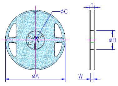
| Type | A | B | C | W | T | Quantity (EA) | |
|---|---|---|---|---|---|---|---|
| Paper Tape (Type B) | Polystyrene Tape (Type A) | ||||||
| ML03 | 178 ± 1 | 60.0 + 0.5 | 13.0 ± 0.2 | 9.00 ± 0.5 | 12.0 ± 0.15 | 4,000 | - |
| ML05 (≤ 2.2uH) | 178 ± 1 | 60.0 + 0.5 | 13.0 ± 0.2 | 9.00 ± 0.5 | 12.0 ± 0.15 | 4,000 | - |
| ML05 (≥ 2.7uH) | 178 ± 1 | 60.0 + 0.5 | 13.0 ± 0.2 | 9.00 ± 0.5 | 12.0 ± 0.15 | - | 3,000 |
| ML06 | 178 ± 1 | 60.0 + 0.5 | 13.0 ± 0.2 | 9.00 ± 0.5 | 12.0 ± 0.15 | - | 3,000 |
| MLH05 | 178 ± 1 | 60.0 + 0.5 | 13.0 ± 0.2 | 9.00 ± 0.5 | 12.0 ± 0.15 | 4.000 | - |
| MLH06 | 178 ± 1 | 60.0 + 0.5 | 13.0 ± 0.2 | 9.00 ± 0.5 | 12.0 ± 0.15 | - | 3,000 |
| MLH08 | 178 ± 1 | 60.0 + 0.5 | 13.0 ± 0.2 | 9.00 ± 0.5 | 12.0 ± 0.15 | - | 3,000 |
Tape Specifications & Tape Material (Unit : mm)

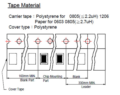
| Type | A | B | T | W | P | F | K | Tape Type |
|---|---|---|---|---|---|---|---|---|
| ML03 | 1.05 | 1.85 | 0.95 | 8.0 | 4.0 | 3.5 | - | B |
| ML05(≤ 2.2uH) | 1.50 | 2.42 | 0.95 | 8.0 | 4.0 | 3.5 | - | B |
| ML05(≥ 2.7uH) | 1.50 | 2.35 | 1.45 | 8.0 | 4.0 | 3.5 | 0.22 | A |
| ML06 | 1.88 | 3.50 | 1.27 | 8.0 | 4.0 | 3.5 | 0.22 | A |
| MLH05 | 1.45 | 2.25 | 0.95 | 8.0 | 4.0 | 3.5 | - | B |
| MLH06 | 1.88 | 2.40 | 1.23 | 8.0 | 4.0 | 3.5 | 0.23 | A |
| MLH08 | 2.20 | 2.85 | 1.40 | 8.0 | 4.0 | 3.5 | 0.23 | A |
Note:
1. Please make sure that your product is has been evaluated and confirmed against your specifications when our product is mounted to your product.
2. Do not knock nor drop.
3. All the items and parameters in this product specification have been prescribed on the premise that our product is used for the purpose, under the condition and in the environment agreed upon between you and us. You are requested not to use our product deviating from such agreement.

Resistor de precisão de filme fino 0,01%, TC2ppm, wirebondale, Anti-Corrosivo, MELF. Detecção de corrente,...
consulte Mais informação
Indutores de chip de alta frequência cerâmicos, de tamanho pequeno até 01005. Filme fino, multicamada,...
consulte Mais informação
O capacitor cerâmico multicamadas oferece alta voltagem, alta frequência, baixo ruído, alto Q, baixo...
consulte Mais informação