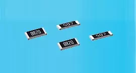
초저항 (금속 스트립) 칩 저항기 (LR 시리즈 LR12FTK3M50)
LR12FTK3M50
금속 저항기
대전류 감지용 금속 스트립 초저 옴 저항기, 고온에 견딜 수 있습니다. 안정된 저항 변동을 위한 낮은 TCR을 가지고 있습니다.
LR Series2512 ±1% 150 1W Series3.5mΩ
| 크기 | 허용오차 | TCR (ppm /℃) | 전력 | 저항 (옴) |
|---|---|---|---|---|
| 2512 | ±1% | 150 | 1W | 3.5m |
고전력 정격 전기 사양
| Item Part No. |
Power Rating at 70°C |
Operating Temp. Range | Resistance Range (mΩ) | TCR (PPM/°C) |
||
|---|---|---|---|---|---|---|
| ±1% | ±3% | ±5% | ||||
| LR12□TDS□□□□ | 2W | -55 ~ +155°C | 0.5, 0.75, 1, 1.5, 2 | ±50 | ||
| LR12□TWS□□□□ | 2W | -55 ~ +155°C | 6, 6.5, 7 | ±75 | ||
| LR12□TES□□□□ | 2W | -55 ~ +155°C | 4, 5, 10 | ±100 | ||
| LR12□TKS□□□□ | 2W | -55 ~ +155°C | 2.5, 3 | ±150 | ||
Operating Current =√(P/R), Operating Voltage=√(P*R)
☑ Viking has the ability of manufacture following options based on customer's requirement..
저항 코드 예시
| Resistance | 1mΩ | 2mΩ | 7mΩ | 10mΩ |
|---|---|---|---|---|
| Codes | R001 | R002 | R007 | R010 |
환경 특성
| Item/th> | Requirement | Test Method |
|---|---|---|
| Temperature Coefficient of Resistance (T.C.R.) | As Spec. | MIL-STD-202 Method 304 +25~125°C, 25°C is the reference temperature |
| Short Time Overload | ±0.5% | JIS-C-5201-1 5.5 5*rated power for 5 seconds |
| ±1% | MIL-STD-202 Method 108A 70±2°C, RCWV for 1000 hrs with 1.5 hrs “ON” and 0.5 hr “OFF” |
|
| Dry Heat | ±1% | JIS-C-5201-1 7.2 at +170°C for 1000 hrs |
| Solderability | 95% min. coverage | MIL-STD-202 Method 208H 245±5°C for 3 seconds |
| Resistance to Soldering Heat | ±0.5% | MIL-STD-202 Method 210E 260±5°C for 10 seconds |
| Thermal Shock | ±0.5% | MIL-STD-202 Method 107G -55°C ~ 150°C, 100 cycles |
RCWV(Rated Continuous Working Voltage)= √(P*R) or Max. Operating Voltage whichever is lower.
☑ Storage Temperature: 15~28°C; Humidity < 80%RH
리플로우
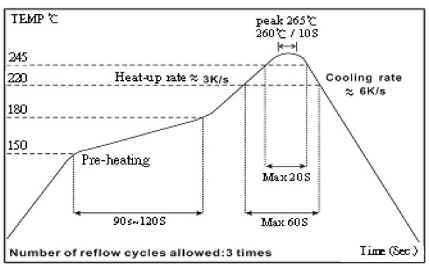
☑ Green coating ”Reflow Air Convection ”is available
☑ Green coating can't be working with wave soldering bath
측정
1. LR12 4-wire precision measurement (Black Coating)
■ Equipment: ADEX AX-1152D DC Low Ohm Meter
■ Excitation Current: 3A (0.5mΩ~1.5 mΩ)
1A (2mΩ~10mΩ)
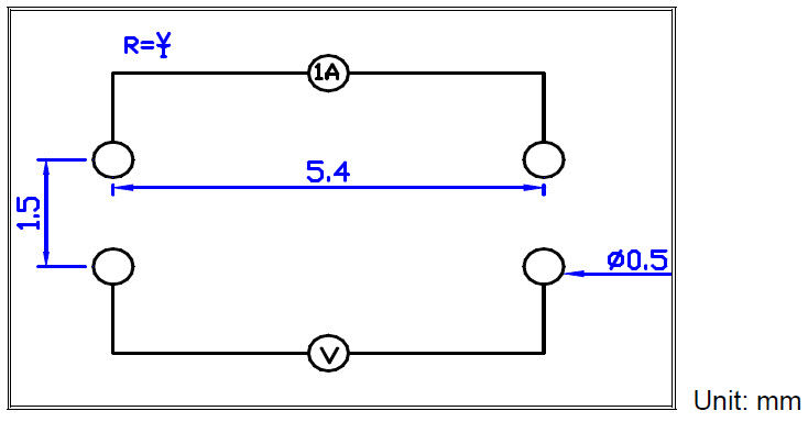
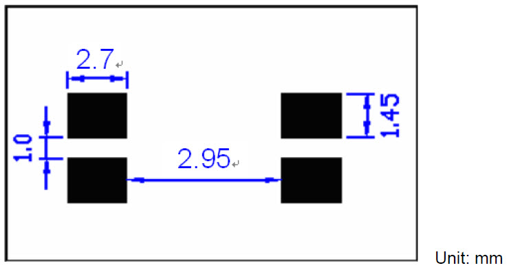
2. LR12 4-wire pad layout (recommended for precision current sensing)
■ Note: No circuits between pads to avoid short circuit
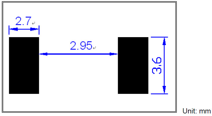
3. LR12 2-wire pad layout
■ Note: No circuits between pads to avoid short circuit
포장
Embossed Plastic Tape Specifications

| Type | Resistance (mΩ) |
A | B | W | E | F | P0 | P1 | P2 | ΦD0 | ΦD1 | T | Quantity (EA) |
|---|---|---|---|---|---|---|---|---|---|---|---|---|---|
| LR06 | 0.5 - 10 | 1.90±0.1 | 3.60±0.1 | 8.0±0.2 | 1.75±0.1 | 3.5±0.05 | 4.0±0.1 | 4.0±0.1 | 2.0±0.05 | 1.55±0.05 | 1.0min. | 0.87±0.1 | 2,000 |
| LR10 | 0.5 - 10 | 2.85±0.1 | 5.55±0.1 | 12.0±0.2 | 1.75±0.1 | 5.5±0.05 | 4.0±0.1 | 4.0±0.1 | 2.0±0.05 | 1.55±0.05 | 1.4min. | 0.85±0.1 | 2,000 |
| LR12 | 0.50 - 0.75 | 3.40±0.1 | 6.75±0.1 | 12.0±0.1 | 1.75±0.1 | 5.5±0.05 | 4.0±0.1 | 4.0±0.1 | 2.0±0.05 | 1.55±0.05 | 1.4min. | 1.45±0.2 | 2,000 |
| 1 - 10 | 0.81±0.1 |
- The cumulative tolerance of 10 sprockets hole pitch is ± 0.2mm.
- Carrier camber shall be not more than 1mm per 100mm through a length of 250mm.
- A & B measured 0.3mm from the bottom of the packet.
- T measured at a point on the inside bottom of the packet to the top surface of the carrier.
- Pocket position relative to sprocket hole is measured as the true position of the pocket and not the pocket hole.
코드
- 3M50
주요 제품


