AUTOMOTIVE APPLICATIONS
Thin film Precision resistor 0.01%, TC2ppm, wirebondale, Anti-Crossive, MELF. Current sensing, Metal...
Read MoreThin film ceramic chip inductor, high frequency, RF inductor for high SRF, Excellent Q , superior temperarture tability. Photolithographic single layer ceramic chip. Stable inductance in hihg frequency circuit. High stable design for critical needs. small size to 01005/0201/0402
AL Series0201 ±0.1nH 1.7nHμH 0.55 Ω 200mA 8 / 500MHz 9GHz
| Size | Tolerance | Inductance | DCR (Ω) max. | IDC (mA) | Q | SRF |
|---|---|---|---|---|---|---|
| 0201 | ±0.1 | 1.7nH | 0.55 | 200 | 8 / 500MHz | 9GHz |
| Item | Requirement | Test Method |
|---|---|---|
| Inductance | As Spec. | Measuring equipment and fixture: 0201: HP4287+Agilent 16196C 0402: HP4287+Agilent 16196B |
| Insulation Resistance | >1000MΩ | MIL-STD-202 Method 302 Apply 100VDC for 1minute |
| Damp Heat with Load | Δ L ≤ 10% | MIL-STD-202 Method 103B 40 ± 2°C, 90 ~ 95% R.H. Max. working voltage for 1000 hrs with 1.5 hrs “ON” and 0.5 hrs “OFF” |
| Bending Strength | As Spec. | JIS-C-5201-1 4.33 Bending Amplitude 3mm for 60 seconds |
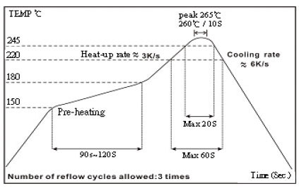
| Solderability | 95% min. coverage | MIL-STD-202 Method 208H 245 ± 5°C for 3 seconds |
| Resistance to Soldering Heat | Δ L ≤ 10% | MIL-STD-202 Method 210E 260 ± 5°C for 10 seconds |
| Dielectric Withstand Voltage | >100V | MIL-STD-202 Method 301 Apply 100VA (rms) for 1minute |
| High Temperature Exposure | Δ L ≤ 10% | MIL-STD-202 Method 108 125 ± 3°C 1000 hours |
| Low Temperature Storage | Δ L ≤ 10% | IEC 60068-2-1 Expossed to a temperature of -55 ± 3°C for 2H |
| Temperature Cycle | Δ L ≤ 10% | JESD22 Method JA-104 -55°C to 125°C, 10 cycles |
☑ Storage Temperature: 15 ~ 28°C; Humidity < 80%RH
☑Shelf Life: 2 years from production date.

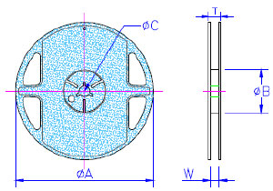
Reel Specifications & Packaging Quantity (Unit : mm)
| Type | Ø A | Ø B | Ø C | W | T | Quantity (EA) |  |
|---|---|---|---|---|---|---|---|
| AL01 | 178 ± 1.0 | 60.0+1.0 | 13.5 ± 0.70 | 9.5 ± 1.0 | 11.5 ± 1.0 | 10,000 | |
| AL02 | 178 ± 1.0 | 60.0+1.0 | 13.5 ± 0.70 | 9.5 ± 1.0 | 11.5 ± 1.0 | 10,000 |
Paper Tape Specifications

| Type | A | B | W | E | F | P0 | P1 | P2 | Ø D0 | T |
|---|---|---|---|---|---|---|---|---|---|---|
| AL01 | 0.40 ± 0.05 | 0.70 ± 0.05 | 8.00 ± 0.10 | 1.75 ± 0.05 | 3.50 ± 0.05 | 4.00 ± 0.10 | 2.00 ± 0.05 | 2.00 ± 0.05 | 1.55 ± 0.03 | 0.42 ± 0.02 |
| AL02 | 0.70 ± 0.05 | 1.16 ± 0.05 | 8.00 ± 0.10 | 1.75 ± 0.05 | 3.50 ± 0.05 | 4.00 ± 0.10 | 2.00 ± 0.05 | 2.00 ± 0.05 | 1.55 ± 0.05 | 0.43 ± 0.03 |
Remark: Test Method
Test direction: Bar mark faces left

Thin film Precision resistor 0.01%, TC2ppm, wirebondale, Anti-Crossive, MELF. Current sensing, Metal...
Read More
Ceramic high frequency chip inductors, small size to 01005. Thin film, multilayer, wirewound , ferrite...
Read More
Multilayer Ceramic capacitor offers high Voltage, high frequency, low noise, High Q, Low TCR. NPO, X7R,...
Read More